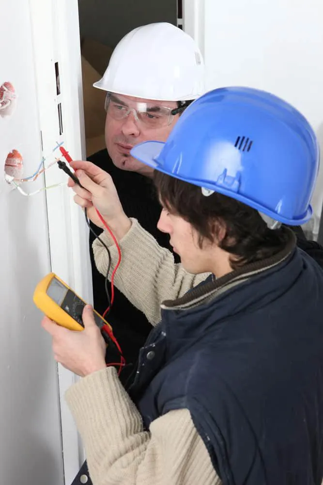
Test przewodnika-Obecnie elektronika jest wszędzie, zarówno w budynkach komercyjnych, jak i mieszkalnych Oznacza to, że przerywacze, przełączniki, przekaźniki i inne połączenia elektryczne działają całodobowo, aby zapobiec uszkodzeniom elektrycznym Jednakże, gdy dwa przewody stykają się, można przewidzieć, że będą jakieś rezystancje Zbyt duża oporność może spowodować przerwy w zasilaniu i inne awarie elektryczne Dlatego te połączenia elektryczne muszą być regularnie utrzymywane To jest miejsce do testowania przewodów Przeczytaj dalej, aby dowiedzieć się więcej na temat testów ductor
Co to jest test przewodnika
Test przewodnika, nazywany również testem rezystancji styków, polega na pomiarze rezystancji wykrywanej w złączach elektrycznych, takich jak połączenia kablowe, złącza i sekcje szyn zbiorczych.
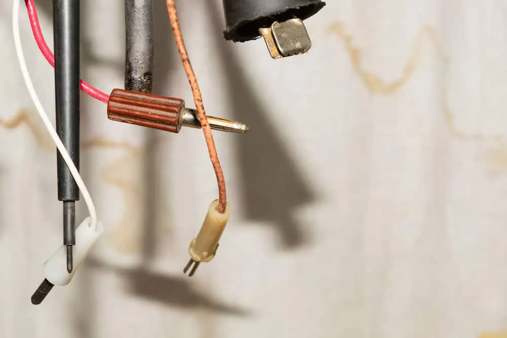
Rezystancja styków pojawia się wtedy, gdy urządzenie elektryczne ogranicza przepływający przez nie prąd lub stawia mu opór. Może również występować w miejscu zetknięcia się styków różnych urządzeń.
W złączach elektrycznych może dochodzić do korozji styków, poluzowania połączeń lub utraty właściwego docisku złącza. Co więcej, rosnąca rezystancja obniża obciążalność prądową, co prowadzi do poważnych przerw w zasilaniu, zaniku faz na stykach, a nawet pożarów. Na szczęście testy rezystancji styków pozwalają utrzymać rezystancję na akceptowalnym poziomie i zapobiec ograniczeniu przepływu prądu.
Test przewodnika-Czym jest miernik rezystancji styków?
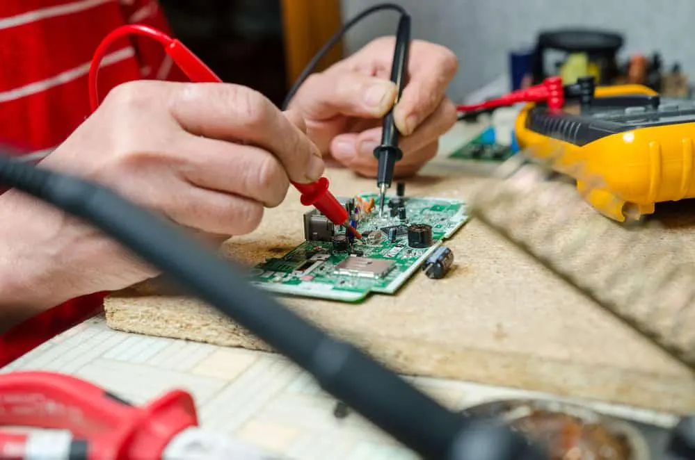
Testy przewodnika przeprowadza się za pomocą specjalistycznego przyrządu zwanego mikroomomierzem (ductor tester). Urządzenie to mierzy rezystancję styków elektrycznych w pojedynczym połączeniu lub w całym obwodzie. Wyniki podawane są w omach — jednostce nazwanej na cześć słynnego niemieckiego fizyka Georga Simona Ohma.
Miernik składa się z amperomierza DC, rezystora oraz baterii 3 V lub wewnętrznego źródła zasilania. Przyrządy te występują zwykle w różnych rozmiarach, w zależności od zakresu wykonywanych pomiarów. Omomierze dzielą się przy tym na kilka odmian: mikroomomierze, miliomomierze i megaomomierze.
1. Omomierz szeregowy
W tym omomierzu obwód pomiarowy rezystancji jest połączony z miernikiem szeregowo. Układ składa się z 4 rezystorów pełniących różne funkcje. Przykładowo R1 ogranicza przepływ prądu, R2 służy do zerowania wskazania, RX to rezystancja mierzona (nieznana), a RM to rezystor wewnętrzny. Przyrząd zawiera ponadto wewnętrzną baterię o napięciu E oraz dwa zaciski wyjściowe (A i B).
Wartości rezystancji styków mierzy się w układzie, w którym R2 jest połączony szeregowo z R1, a bateria podłączona do zacisków A i B. Jeżeli zaciski pozostają rozwarte, prąd nie płynie, a wskazówka odchyla się w stronę symbolu nieskończoności, sygnalizując nieskończoną rezystancję. W zależności od wykonanych połączeń można jednak uzyskiwać różne odczyty rezystancji.
2. Test przewodnika-Omomierz bocznikowy
W omomierzu bocznikowym obwód pomiarowy jest połączony równolegle z RX i baterią. Miernik ten przydaje się przede wszystkim do pomiaru małych wartości rezystancji. W omomierzu bocznikowym najważniejszą rolę odgrywają zazwyczaj RM, R2 oraz E (bateria). Z kolei RX podłącza się do zacisków A i B.
Jednak w przeciwieństwie do omomierza szeregowego symbol nieskończoności znajduje się tu po prawej stronie skali, a zero po lewej. Gdy RX wynosi zero, odczyt rezystancji również jest zerowy, natomiast przy rozwartych zaciskach wskazówka odchyla się ku symbolowi nieskończoności, sygnalizując nieskończoną rezystancję. Co istotne, podczas tego testu należy stosować wyłącznik, aby zapobiec niekontrolowanemu przepływowi prądu.

Jak określić kryteria testu rezystancji styków
Test rezystancji styków zależy od kilku czynników, w tym rodzaju połączenia (spawane, zaciskane czy skręcane śrubami), siły docisku styków oraz powierzchni styku metalu. Czynniki te mogą się jednak różnić w zależności od urządzenia, materiału styków lub zaleceń producenta.
Nie istnieje norma określająca minimalną rezystancję styków, natomiast jej maksymalna wartość może być różna u poszczególnych producentów. Z tego względu przed wykonaniem testu zawsze warto skonsultować się z producentem. Czasami wynik pomiaru rezystancji styków można połączyć z termowizją, aby wykryć przegrzewające się połączenia i newralgiczne miejsca w układach szyn zbiorczych.
Test przewodnika-Procedura badania rezystancji styków
Cała procedura obejmuje dwa etapy: oględziny oraz badanie przyrządowe.
Podczas oględzin sprawdza się wyłącznik pod kątem uszkodzeń spowodowanych łukiem elektrycznym, zużyciem eksploatacyjnym lub odkształceniem styków. Celem jest wykrycie i usunięcie wszelkich potencjalnych problemów, które mogłyby ograniczyć prawidłowy przepływ prądu.
Badanie przyrządowe opiera się na omomierzu. Do styków doprowadza się prąd o ustalonej wartości i mierzy spadek napięcia na obwodzie. Prąd pomiarowy może wynosić od 100 A do 200 A lub więcej. Gdy omomierz poda dokładny wynik pomiaru, na jego podstawie oblicza się rezystancję. Uzyskaną wartość można porównać z danymi producenta oraz wcześniejszymi zapisami, aby utrzymać rezystancję styków na akceptowalnym poziomie.
Należy pamiętać, że oględziny i badanie przyrządowe prowadzi się równolegle, aby mieć pewność, że obwód jest w idealnym stanie.
Test rezystancji styków: przewodnik krok po kroku
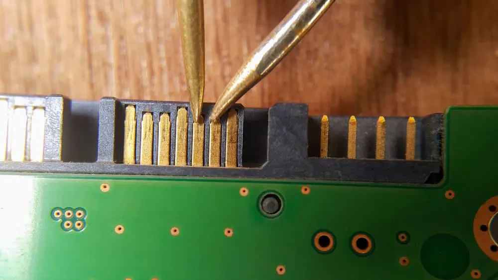
Zanim przejdziemy dalej: do wykonania testu rezystancji styków niezbędny jest omomierz lub mikroomomierz (ductor tester). Większość osób wybiera mikroomomierz, ponieważ zapewnia dokładniejszy pomiar. Przyrząd mierzy rezystancję styków metodą czteroprzewodową (Kelvina), opartą na spadku napięcia DC, dzięki czemu eliminuje wpływ rezystancji styków pomiarowych i przewodów prądowych na wynik.
W teście wykorzystuje się dwa przewody napięciowe do pomiaru spadku napięcia oraz dwa przyłącza prądowe wymuszające przepływ prądu. Pamiętaj, że wszystkie przewody napięciowe należy podłączać możliwie najbliżej badanego połączenia. Przewody te powinny też znajdować się wewnątrz obwodu utworzonego przez podłączone przewody prądowe.
Sterowany mikroprocesorem mikroomomierz obliczy następnie rezystancję styków i wyeliminuje powodowane przez nią błędy. Po uzyskaniu wyników pomiary rezystancji styków dodaje się do całkowitego spadku napięcia zmierzonego osobno.
Praktyczna wskazówka: od wyniku końcowego należy odjąć wartość termoelektrycznej siły elektromotorycznej (SEM), aby uniknąć przekłamań. Wielkość termicznej SEM można zmierzyć różnymi metodami, m.in. przez odwrócenie polaryzacji. Ponadto jeśli przy małych prądach pomiarowych uzyskujesz zaniżone odczyty, warto powtórzyć test z wyższym prądem. Wyższe prądy ograniczają bowiem problemy ze stykiem i skutki utleniania zacisków.
Zawsze sprawdzaj też, czy odczyty są zgodne z wcześniejszymi zapisami i wartościami podanymi przez producenta. Co więcej, wszystkie wyniki warto dokumentować na potrzeby przyszłych porównań. Wreszcie, aby zachować powtarzalność wyników, testy należy wykonywać w tej samej pozycji i w tych samych warunkach.
Podsumowanie
Podsumowując, testy rezystancji styków są niezbędne, aby utrzymać połączenia elektryczne w nienagannym stanie. Nikt nie chce doświadczać nieoczekiwanych przerw w zasilaniu, awarii sprzętu ani — co gorsza — pożarów spowodowanych usterkami wyłączników. Dlatego warto regularnie wykonywać testy i wymieniać styki zawsze, gdy zajdzie taka potrzeba.
Możesz też skontaktować się z nami we wszystkich kwestiach związanych z okablowaniem i wiązkami przewodów. Nasza firma szczyci się dziesięcioletnim doświadczeniem w produkcji wiązek kablowych.